
Get a Quote

+86-18862679789


admin@evertopest.com

the extrusion performance differ with different rotation directions?
In material mixing processing, the performance of the twin-screw extruder directly determines the material mixing effect, production efficiency and final product quality. According to the direction of screw rotation, twin-screw extruders are divided into co-rotating twin-screw extruders and counter-rotating twin-screw extruders, and the main difference between the two lies in the direction of screw rotation. What seems to be just a difference in the direction of rotation results in significant distinctions between the two in processing characteristics, mixing capacity, and product compatibility.
The main difference between co-rotating twin-screw and counter-rotating twin-screw lies in the interaction process of the screws:
• When the two threads of a co-rotating twin-screw push the material, their thrust is superimposed;
• When the two thread lines of a counter-rotating twin-screw push material, their thrusts cancel each other out.
This determines the basic working principle and performance characteristics of both co-rotating and counter-rotating twin-screws. 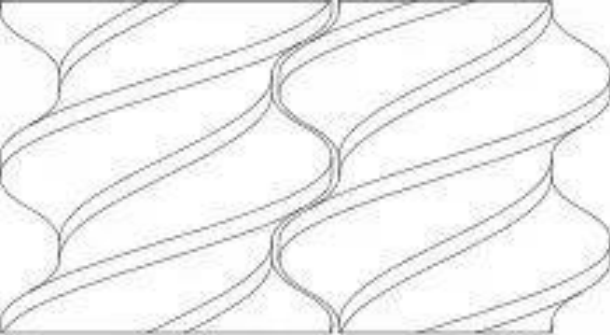
Figure 4 Fit of co-rotating twin-screw
The mating mode of the co-rotating twin-screw is shown in Figure 4. The two screws of the co-rotating twin-screw rotate in the same direction, and the screw threads are both right-handed. The determination of the material conveying direction is the same as that of the single-screw.
The mating mode of the counter-rotating twin-screw is shown in Figure 5. The two screws of the counter-rotating twin-screw rotate in opposite directions, and the threads of the two screws rotate in opposite directions. The two screws rotate outward. That is, along the extrusion direction, the right side is the left-hand screw, which rotates clockwise, and the left side is the right-hand screw, which rotates counterclockwise.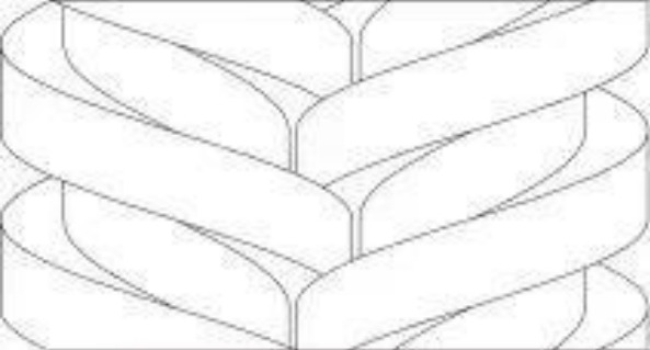
Figure 5 Counter-rotating twin-screw fit
Analysis of simulation experiment results
Physical field
1
Pressure field
As seen from the pressure cloud map (Figure 6) and the pressure variation curve (Figure 7) :
In the co-rotating twin-screw extrusion process, the pressure in the flow channel fluctuates. Referring to the structure after the co-rotating twin-screw fit (Figure 4), it is found that the pressure fluctuation fluctuates up and down with the position of the screw ridge. This is because the screw ridge is a high protruding part of the screw surface, and the extruded material is subjected to stronger extrusion and shear forces when passing through the screw ridge, so the pressure is often relatively high at the position of the screw ridge.
In counter-rotating twin-screw extrusion, the pressure in the runner first increases and then decreases along the extrusion direction, and local high pressure occurs at the middle position. Referring to the structure of the counter-rotating twin-screw fit (Figure 5), it is found that the local high pressure occurs at the meshing point along the middle of the extrusion direction. This is because the two screws rotate in opposite directions, and the material flow is uneven or blocked during the extrusion process, which accumulates at the middle position and then forms the local high pressure in the channel.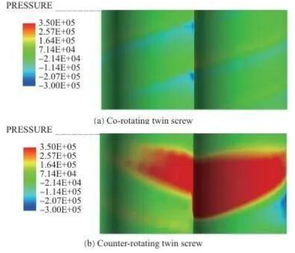
Figure 6 Pressure cloud diagram in the runner during the extrusion process
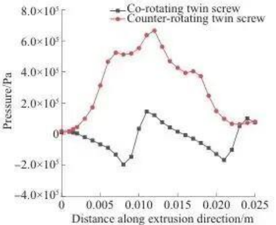
Figure 7 Pressure variation curve
2
Shear rate field
As seen from the shear rate cloud (Figure 8) and the shear rate variation curve (Figure 9) :
In both co-rotating twin-screw extrusion and counter-rotating twin-screw extrusion, the shear rate is higher at the screw ridge and lower at the screw groove. The reason for this phenomenon is that the material flows faster in the narrow gaps, and the gap between the screw ridges and the inner wall of the barrel is smaller, so the shear rate is higher, while the gap between the screw grooves and the inner wall of the barrel is larger, so the shear rate is lower.
The local high shear rate in the counter-rotating twin-screw is caused by leakage.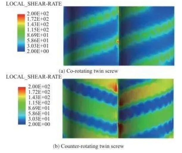
Figure 8 Cloud of shear rate during extrusion
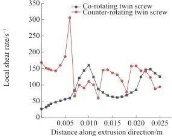
Figure 9 Shear rate variation curve
Mixing is mainly divided into distributive and dispersive mixing.
Distributed mixing is used to describe the distribution process of the material, in which the material is constantly rearranged and directed under the push of the screw rotor;
Dispersive mixing is used to describe the process in which the size of the material changes as the material particles are constantly stretched and sheared. The tracer particle method was used to conduct mathematical statistics on trajectory parameters such as residence time, distribution index, separation scale, and maximum shear stress distribution to analyze the differences in mixing performance between co-rotating twin-screw and counter-rotating twin-screw.
Axial mixing performance
Residence time distribution is an important indicator for measuring the axial mixing performance of screw elements. It describes the distribution of residence time of materials in twin-screw extruders in two forms: cumulative residence time distribution function and residence time distribution function, which are respectively expressed by probability function and probability density function.
1 Cumulative dwell time distribution
The cumulative dwell time distribution curve (Figure 10) describes the cumulative probability distribution of the dwell time of the fluid or material in the extruder.
As shown in Figure 10, in the co-rotating twin-screw, the time when the tracer particles first exit the runner is 1.00 s, the time when they completely exit the runner is 54.82 s, and the width of the dwell time distribution is 53.82 s.
In the counter-rotating twin-screw, the time for the tracer particles to first flow out of the channel is 1.48 seconds, the time for them to completely flow out of the channel is 59.80 seconds, and the width of the residence time distribution is 58.32 seconds.
The cumulative dwell time distribution curve of the co-rotating twin-screw is above the cumulative dwell time of the co-rotating twin-screw, and a higher curve indicates that more particles are flowing out of the channel at a given moment.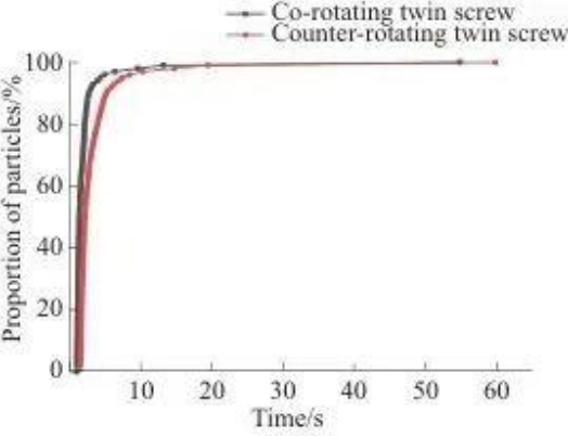
Figure 10 Distribution of cumulative dwell time
2 Distribution of dwell time
The residence time probability density distribution curve describes the probability distribution of the residence time of the material in the extruder over different time periods. A higher probability density means a greater probability of material residence during that period, while a lower probability density indicates a relatively shorter residence time. From the probability density function of the residence time distribution (Figure 11), it is known that:
In the co-rotating twin-screw, the majority of particles are concentrated at 1.00 to 1.99 seconds, and in the counter-rotating twin-screw, the majority of particles are concentrated at 1.48 to 2.97 seconds. The corresponding curve of the co-rotating twin-screw is further to the left, and the peak is higher, indicating that the conveying capacity of the co-rotating twin-screw is stronger. The reason for this phenomenon may be that during the co-rotating twin-screw extrusion process, the material is forcibly transported along an "∞" shaped path by the screw.
In counter-rotating twin-screw extrusion, the material moves in a "C" shape and mixes and reacts repeatedly in the C-shaped chamber, resulting in an extended dwell time.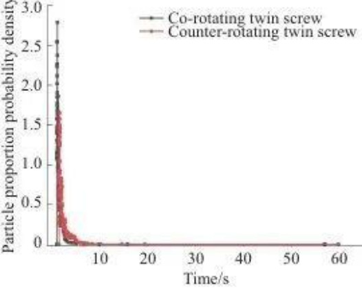
Figure 11 Distribution of dwell time
Distributed mixing performance
1 Distribution index
Distribution indices describe the rheological properties and flow behavior of extruded materials. It can be seen from the distribution index curve (Figure 12) that the distribution uniformity of the counter-rotating twin-screw is better than that of the co-rotating twin-screw.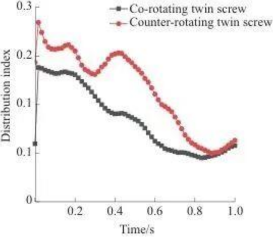
Figure 12 Distribution Index
2 Separation scale
Separation scales characterize distributed mixing processes. Figure 13 shows the separation scale curve. At the initial moment, the two particles are on either side of the inlet, so the separation scale value is large. As time increases, the separation scale decreases under the screw mixing effect, the curve drops, the degree of distribution mixing of surface particles deepens gradually, and there is a fluctuation phenomenon during the process, which is caused by the aggregation of particles during the flow process.
The separation scale curve of the co-rotating twin-screw is always below that of the counter-rotating twin-screw, indicating that it is more uniform in distribution.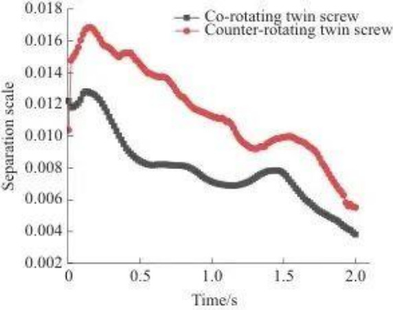
Figure 13 Separation scale
In co-rotating twin-screw extrusion, the two screws rotate in the same direction and form a strong shearing effect at the meshing point, and the material exchanges multiple times between the screws, which helps to achieve uniform distribution mixing.
In counter-rotating twin-screw extrusion, most of the material is retained in the C-shaped chamber, with only a small amount of material flowing out of the gap to be subjected to shearing and stretching. The sealing is good, reducing the irregular flow of the material in the runner, and thus the uniformity of the mixture is also reduced.
Dispersion and mixing performance
The dispersion and mixing process is a process in which the particle size keeps decreasing, and the shear and tensile forces that the material particles are subjected to play a significant role in this process.
The maximum shear stress experienced by the tracer particle indicates the shear process that the tracer particle undergoes during the twin-screw extrusion process. The greater the proportion of tracer particles experiencing high shear, the better the screw dispersion effect.
Figure 14 shows the maximum shear stress probability curve. As can be seen from Figure 14, the curve corresponding to the counter-rotating twin-screw is above that of the co-rotating twin-screw.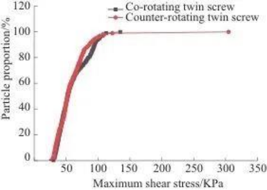
Figure 14 Maximum shear stress probability
Figure 15 shows the maximum shear stress probability density curve. From Figure 15, it can be seen that the maximum shear stress endured by the particle is concentrated at the peak of the curve protrusion.
The two curve features indicate that the counter-rotating twin-screw has a stronger dispersion ability and can provide stronger shear and tensile effects than the co-rotating twin-screw.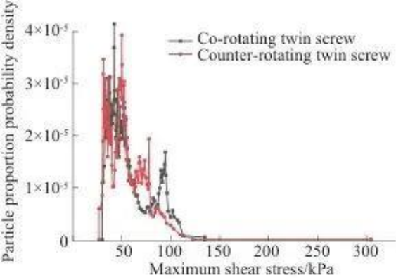
Figure 15 Maximum shear stress probability density
Analysis of Experimental Results
Tensile impact test analysis
Figures 17 and 18 show tensile and impact test data, respectively.
The tensile strength and tensile strain at break of the material splines extruded by co-rotating twin-screw extrusion were slightly higher than those extruded by counter-rotating twin-screw extrusion.
The impact energy absorption and impact strength of the material splines extruded by the counter-screw extrusion are slightly higher than those extruded by the co-screw extrusion.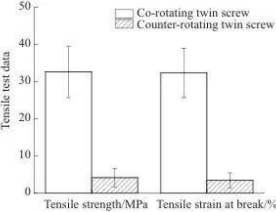
Figure 17 Tensile test data
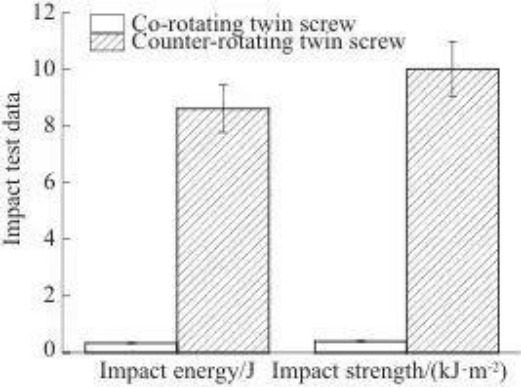
Figure 18 Impact test data
Rheological test results
The rheological properties of polymers are typically reflected in storage modulus (G'), loss modulus (G'), and composite viscosity (η*). The storage modulus reflects the elasticity of the material, the loss modulus reflects the viscosity of the material, and the composite viscosity reflects the molecular weight. The fluidity of the polymer melt depends on the ability of the molecular chain segments to move. Screw extrusion changes the molecular structure of PLA, causing its molecular chains to break and reducing its viscosity.
Figure 19 shows the curve of composite viscosity η* with angular frequency. It can be seen from Figure 19 that η* decreases with the increase of angular frequency.
Because of the structural difference, the counter-rotating twin-screw has a stronger dispersion and mixing ability, and the molecular chain breaks more fully. Therefore, the η* of the material extruded by the counter-rotating twin-screw is lower than that of the co-rotating twin-screw.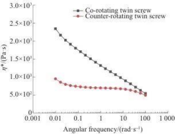
Figure 19 Curves of η* with angular frequency
Summary
Advantages of co-rotating twin-screw extruders:
• The flow field (especially the pressure) is relatively stable.
• Extremely strong distribution mixing ability, high uniformity of material distribution.
• Short material residence time and high conveying efficiency facilitate the processing of heat-sensitive materials and reduce the risk of thermal degradation.
• The extruded products have better tensile properties.
Advantages of counter-rotating twin-screw extruders:
• Stronger pressure-building capacity (but beware of possible local high pressure).
• More intense shearing, superior dispersion and mixing ability. It can provide a stronger stretching effect.
• Longer dwell time and wider distribution of materials, suitable for processes that require sufficient reaction or mixing time.
• Extruded products have higher impact strength and lower melt viscosity (more thorough molecular chain breaks).

Tanshang Village Industrial Clusters, Ganghua Road,Jingang Town, Zhangjiagang City, Jiangsu Prvince, China

+86-18862679789
+86-15555592012
+86-13140831504

+86-0512-56720211

admin@evertopest.com
admin@acp-line.com
Copyright © Zhangjiagang Hongyang Machinery Equipment Co., Ltd. All Rights Reserved. Custom Composite Panel Production Line Manufacturers

 English
 Español
 русский
 عربى
عربى