


Get a Quote

+86-18862679789


admin@evertopest.com

Content
A project engineer comparing two offers for a 2,600 mm cast film line recently found a price gap large enough to buy a small extruder, even though both lines promised the same output and the same roll stack. The real difference sat in the cast film extrusion die type quoted in each offer, and with it the manifold design, the lip adjustment hardware and the gauge uniformity the line could hold after the third shift. In cast film production the die is where one molten stream becomes a flat, metered web, so it is the component that converts extruder stability into sellable film.
The practical conclusion comes first. For most wide-web work, a coat-hanger manifold die with an adjustable restrictor bar and flexible lips is the default engineering choice. A straight T-slot die remains a sensible, lower-cost option for narrower webs and moderate tolerances. Fishtail dies survive mainly on short-width, budget-conscious lines. Deckle systems add width flexibility when one die must serve many orders, and multilayer coextrusion dies or feedblocks are the correct answer when the product needs barrier, skin or tie layers.
This article walks through the main die types, the geometry that actually controls film quality, single-layer and multilayer configurations, indicative width capabilities, selection and procurement points, maintenance routines, and the questions buyers ask most often. The same logic applies whether the downstream product is CPP packaging film, breathable film, extrusion coating, or the polymer core extruded between aluminum skins on a metal composite panel line, which is the field where our own T-die and composite panel production line engineering is applied every day.
The cast film extrusion die type you choose defines the achievable gauge profile, width flexibility and layer structure of the entire line, so it should be specified before the extruder is, not after.
In a cast film or extrusion lamination line, the die sits at the hinge between melt preparation and product forming. Upstream, an extruder plasticizes the resin, a screen changer removes contaminants, and on quality-critical lines a melt pump and static mixer stabilize pressure and temperature. Downstream, the molten web is pulled onto a chill roll or a multi-roll stack, passes a thickness scanner, and is trimmed, treated and wound. Between those two worlds stands the die, and its only job is to turn one rotating stream of melt into a flat web whose output per centimeter of width never changes.
Inside the body, five stages do that work in sequence.
Typical working figures help to size expectations. Cast film dies serving products between roughly 12 and 150 microns are usually built with lip gaps in the region of 0.25 mm to 1.0 mm, because die swell and draw-down between the lips and the chill roll reduce the web well below the exit gap. The body is divided into independently controlled heating zones so the temperature profile can be trimmed along the width, and internal melt pressure is monitored because its stability predicts gauge stability. These are orientation values rather than guarantees, and the exact figures depend on resin, output and the design philosophy of the die manufacturer.
It also helps to place the cast film die in the wider die family tree. Blown film dies are annular and form a tube, while profile and pipe dies shape a continuous cross-section. Cast film dies belong to the flat die family, the same family used for slot coating and for extruding sheet and panel cores, which is why the selection logic in this article repeats itself across film, coating and composite panel projects.
A cast film die is a melt distribution and metering instrument; gauge and edge quality are decided by its manifold, land and lips long before the chill roll is involved.
Die makers and die users group flat dies into a handful of working categories. The names describe the manifold shape or the adjustment hardware, and each category implies a different balance between cost, gauge performance and flexibility. The cards below summarize the types you will meet in supplier catalogs, and the table that follows compares them side by side.
A straight circular manifold runs the full width and feeds a secondary distribution channel toward the lips. Simple, robust and easy to strip down for cleaning. Best on narrow to medium webs where tolerance targets are moderate and budget matters.
A teardrop-shaped manifold tapers from the center toward both ends along an angled lead-in land. Flow resistance is equalized across the width, which is why this design dominates wide, high-precision cast film.
The manifold fans out like a fish tail from a central inlet. Compact and inexpensive, but distribution accuracy falls off as width grows, so it is mostly found on narrow lines and entry-level equipment.
An internally adjustable choke bar sits between the manifold and the land. Turning its bolts redistributes flow so operators can correct center-heavy or M-shaped gauge profiles without touching the resin.
The upper lip is divided into segments set by push-pull bolts, or by thermal expansion bolts wired to an automatic gauge control loop. This is the hardware behind closed-loop thickness control.
Internal deckle rods or external deckle plates close off part of the width so one die can produce different web widths. Standard equipment on lines serving many customer width specifications.
Either a feedblock merges layers before a single manifold, or a multi-manifold die carries each layer separately and joins them near the lips. The route to barrier films, skin layers and laminated structures.
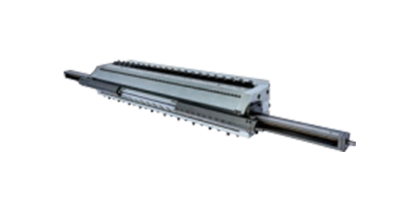 T-Die for PE Sheet ExtrusionA precisely engineered flat die that extrudes molten PE into uniform, smooth-surfaced core sheets for aluminum-plastic panels. Its hanger-type flow channel and polished surfaces make it worth reviewing where sheet thickness stability and multi-layer co-extrusion matter.View Product →
| Die type | Distribution principle | Typical working width | Best suited for | Practical limitations |
|---|---|---|---|---|
| T-slot, T-type die | Straight circular manifold with a secondary channel | Narrow webs up to about 2 m | PE and PP films, lamination and panel core work on tighter budgets | Wider residence time spread, more manual profile tuning |
| Coat-hanger die | Tapered teardrop manifold on an angled land | About 2 m to beyond 3 m | Wide CPP, packaging and technical film lines | Higher purchase cost, longer cleaning work |
| Fishtail die | Fan-shaped expanding manifold | Up to roughly 1.2 m | Narrow webs, short runs, entry-level lines | Uniformity drops quickly with width |
| Restrictor bar die | Bolt-adjustable internal choke above the land | Follows the base die | Correcting center-heavy or M-shaped profiles | Requires skilled setup and good records |
| Flex-lip or automatic die | Segmented upper lip, manual or thermal bolts | Follows the base die | Closed-loop gauge control on quality lines | Higher cost, more components to maintain |
| Deckle die | Internal rods or external plates closing the width | Variable, per order | Order books with many width specifications | Edge quality needs close attention |
| Multilayer coextrusion die | Feedblock or multi-manifold layering | Follows the base die width | Barrier, skin and tie layers, laminates | System complexity, longer cleaning |
If you remember only one rule: width and tolerance requirements select the manifold family, while flexibility requirements decide whether deckles, restrictor bars or automatic lips are added on top of it.
The coat-hanger manifold earns its place through geometry. Melt entering at the center can reach the middle of the lips through a short path, while melt bound for the edges travels much farther. A straight channel would therefore deliver more flow to the center. The coat-hanger design tapers the manifold toward both ends along an angled lead-in land, so every path from inlet to lip exit meets nearly the same hydraulic resistance. The exit velocity profile flattens, and the gauge profile across the width follows it.
The restrictor bar is the practical safety valve on top of that geometry. Even a well-calculated manifold meets real resins at real temperatures, and a center-heavy or M-shaped profile is the usual symptom of a distribution that does not quite match the compound. Turning the restrictor bar bolts chokes or opens selected zones of the channel, redistributing flow without touching the resin or the extruder. During commissioning, restrictor bar and lip adjustments are recorded bolt by bolt, because that record is what makes the next changeover fast instead of experimental.
The land, the parallel channel just before the exit, looks simple but sets behavior. A longer land costs pressure drop but relaxes elastic memory and steadies the web, and cast film dies commonly use lands measured in tens of millimeters. The adjustable lip gap is set wider than the final film gauge, because die swell at the exit and draw-down down to the chill roll shrink the web. How much wider depends on the resin, the melt temperature and the draw ratio, which is why commissioning trials on the real compound matter more than catalog numbers.
Edges deserve their own paragraph because they cause a disproportionate share of waste. At the two ends of the manifold the melt loses the confinement of the flow channel beside it, so a thicker, slower edge bead forms; left untrimmed, it prints a pattern onto the roll stack and disturbs winding. Die makers respond with removable edge inserts, land extensions and carefully designed deckles, and production teams respond with trim knives, which is why a die specified for a given sellable width is usually built wider to absorb the trim.
Residence time is the quiet variable. Dead corners and overly long channels let resin sit and degrade, and the result appears downstream as gels, die lines or yellowing, especially on heat-sensitive materials. Streamlined transitions, polished internals and the right manifold choice keep the spread of residence times narrow. Body material matters just as much: hardened and ground tool steel, polished lands, and quality plating or nitriding protect the precision surfaces. Mineral-filled flame-retardant compounds, such as those used for fire-rated composite panel cores, accelerate land wear, so plating quality and inspection intervals deserve explicit attention whenever such compounds are on the production plan.
Gauge uniformity is designed into the manifold, then defended every shift through restrictor bar and lip settings; treating either half of that pair as optional shows up immediately in the thickness profile.
The single-layer configuration is the baseline: one extruder feeds one manifold and one set of lips. The setup is simple to operate and clean, and it is fully adequate for monolayer films, sheet and the polymer core extruded in composite panel production. Its limits appear the moment the product needs a property that one resin cannot deliver, such as a stiff skin over a soft core or a barrier layer against oxygen and aroma.
The feedblock route places a small distribution module between the extruders and a conventional single-manifold die. The module stacks the layers in the required order and ratio and delivers the combined stream to the die. Investment stays moderate, and layer ratios can be changed by swapping feedblock modules, which is why many three-layer CPP and packaging lines work this way. The compromise is that all layers share one set of lips, and when neighboring resins differ strongly in viscosity or elasticity, interfacial instability can appear as waviness at the layer boundary.
The multi-manifold route gives each polymer its own manifold inside a larger die body, and the layers meet close to the exit. Skin layers keep their own metering, thin barrier layers are protected, and structures with five or seven layers become practical. The costs are equally clear: a heavier, more expensive body, more heating zones and more work at cleaning time. High-barrier films, transparent CPP with quality skins and technical laminates usually justify the investment.
Feedblock plus single manifold die
|
Multi-manifold coextrusion die
|
The same engineering reappears a short distance away in metal composite panel production. On an aluminum composite panel line, the core, whether polyethylene or a mineral-filled flame-retardant compound, is extruded as a continuous sheet through a T-die and laminated between two aluminum skins with adhesive film in the same line. Here the die works against different economics: the gauge of the core directly sets panel flatness and weight, filled compounds raise wear and viscosity questions, and output stability matters because the lamination nip tolerates little variation. Lines such as a dedicated ACP production line therefore treat die selection and melt conditioning as core engineering decisions rather than accessory purchases.
 Aluminum Composite Panel Production LineA continuous line that extrudes the PE or mineral-filled flame-retardant core through a T-die and laminates it between aluminum skins with adhesive film. It illustrates how die selection and melt conditioning directly govern panel flatness, gauge and output stability.View Product →
A feedblock wins on flexibility and budget, a multi-manifold die wins on layer quality; in both cases the die, not the extruder, is the precision heart of the layering system.
Width is one of the first numbers a buyer fixes, and it is also the number that narrows the die type decision fastest. The chart below collects indicative maximum productive web widths by die family, based on what is commonly offered in commercial cast film die specifications. Treat the values as orientation points rather than guarantees, because resin viscosity, melt temperature and throughput per centimeter of width all shift the practical limit. A die that runs a low-viscosity polyolefin easily may struggle with a stiff, filled compound at the same width. Even so, the ranking of the die types is stable across suppliers and across years of practice.
Indicative maximum productive web width by die family (meters)
Indicative values compiled from common commercial specifications; confirm final figures with your resin data and the die manufacturer.
The pattern behind the chart is straightforward: as web width grows, the melt must travel farther from the center inlet, and only a properly tapered manifold keeps flow resistance equal along that journey. A fishtail die distributes by simple fanning, so beyond roughly a meter the difference between center and edge becomes visible in the gauge profile. A straight T-slot die pushes the practical ceiling to about two meters, which covers a large share of packaging film and lamination work. The coat-hanger design is what makes three-meter-class webs routine, because its taper is calculated so that every flow path sees nearly identical resistance. Multilayer wide-web dies reach similar or slightly larger widths since they are built on the same manifold principles, with the added task of keeping layer interfaces flat.
Width is not free, and the chart should be read together with the extruder specification, because wider dies demand more output to keep the web stable on the chill roll at a given gauge. Remember trim allowance as well: a die specified at 2,600 mm usually delivers a sellable web somewhat narrower after both edges are trimmed. Deckles reduce the effective width when closed, and the flow disturbance beside a deckle is a common source of edge defects, so buyers who need many widths should discuss deckle design explicitly. For filled, fire-resistant compounds, the practical width for a given die is often lower than for neat polyolefins, because higher viscosity and wall slip behavior change how the melt distributes. When comparing offers from different suppliers, normalize by output per centimeter of width and by target gauge, not by width alone. Finally, ask the manufacturer for reference line data or a gauge profile simulation at your width and material, because a serious die supplier will have both on file.
Above roughly two meters of web width, manifold engineering rather than machine size becomes the binding constraint, which is why coat-hanger and multilayer designs dominate wide cast film lines.
Selection points become concrete when they are attached to a product. The scenarios below cover most of the work flat dies do around the world, from flexible packaging plants to composite panel factories, and each one stresses a different part of the die.
Extrusion coating and lamination deserve special mention because they stress a die differently than free film does. A flat die lays a thin melt film directly onto a moving substrate such as paper, foil or plastic film, at line speeds that leave little room for gauge error, and width changes are frequent when the order book is mixed. On metal-based products the coating step usually works alongside pretreatment and laminating units, and pairing the die with the right upstream pretreatment line and downstream coater keeps adhesion and appearance stable over long runs.
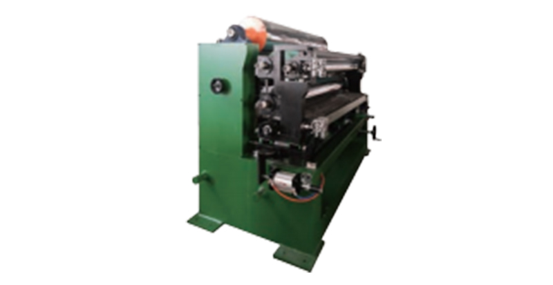 Roller Coater for Metal Coil and SheetA roller-coating system for aluminum coils and sheets with multi-wheel precision control of coating thickness. It pairs with flat dies in extrusion coating lines, delivering uniform finish on both coil surfaces while cutting solvent consumption and VOCs emissions.View Product →
Typical application scenarios
|
Selection points that decide the outcome
|
Whether the purchase goes directly to a die manufacturer or through a supplier or wholesaler, the technical conversation should be identical. The buyer brings resin data, widths, gauge range and output targets; the seller returns a manifold design, a lip system, a heater concept and a profile guarantee in writing. A manufacturer that also builds complete lines, from uncoilers through coaters and roll stacks to stackers, can take responsibility for the whole melt path instead of one component, which shortens commissioning and removes the classic finger-pointing between equipment vendors when something drifts out of tolerance.
Match the die to the product first and the budget second, because the cheapest die that misses the tolerance target is the most expensive equipment in the plant.
Most complaints that reach a die supplier begin as complaints about film. The table below links the visible symptom to the die-related cause that most often lies behind it, and to the first correction worth trying before more drastic measures are taken. In practice, roughly half of these situations are solved with process adjustments, so the die should be the last thing disassembled but the first thing measured.
| Symptom | Typical die-related cause | First correction step |
|---|---|---|
| Center-thick or M-shaped gauge profile | Distribution unbalanced, restrictor bar too open in the middle | Close the restrictor bar gradually at the center and re-check after temperatures stabilize |
| Heavy or ragged edges | Edge bead from manifold end flow, worn or wrongly set deckles | Adjust deckles and edge inserts, then verify trim knife positioning |
| Gauge bands running lengthwise | Damaged lip land or a trapped carbon spot at a fixed position | Inspect and clean the lip, then polish or replace the damaged segment |
| Gels and discoloration | Dead zones and long residence time inside the manifold | Check manifold finish, reduce idle time at temperature, verify every heater zone |
| Periodic thickness surging | Melt pressure fluctuation upstream, worn screen pack or pump | Check screen changer and melt pump before attributing the problem to the die |
| Die lines at fixed width positions | Scratched lip or plating worn through at one spot | Re-polish or re-plate the affected lip surface |
Diagnose from the extruder outward: pressure stability first, temperature second, die hardware last, because disassembly hides more evidence than it reveals.
A cast film die is a ground and plated precision instrument, and it will hold its geometry for decades when handled correctly, or lose its accuracy within a year of rough cleaning and improvised storage. The rhythm below is what experienced lines follow, and it costs far less than a single re-plate.
| Interval | Task | Why it matters |
|---|---|---|
| Every shift | Visual check for leaks at lips and deckles, record lip bolt positions | Leaks mark pressure or damage early, and records make tuning repeatable |
| Weekly | Verify heater zone temperatures against setpoints, inspect wiring | Cold zones distort the gauge and mimic distribution errors |
| Every few weeks | Hot purge and partial clean at operating temperature with brass tools | Prevents carbon build-up without risking the land finish |
| Annually or at resin change | Full strip-down, manifold and land inspection, plating check | Wear on lands shows up first as gauge bands, then as edge problems |
| Every shutdown | Controlled cooling, protective cover, dry storage | Prevents corrosion and accidental impact to the lips |
A few habits make the table work in reality. Never touch the lands with steel scrapers, because a single scratch reproduces itself as a lengthwise gauge band on every meter of film. Follow the bolt loosening and tightening sequence given by the manufacturer, since lips are preloaded and can warp under uneven stress. Keep spare gaskets, heater elements and a set of designated cleaning tools in a fixed place near the line. For mineral-filled flame-retardant compounds, shorten the inspection intervals and watch plating wear closely, because filled compounds are abrasive in a way that neat polyolefins never are. And keep the adjustment records from commissioning with the die, because the fastest restart is the one that begins from documented numbers rather than from memory.
A die that is purged, measured, covered and documented on schedule holds its gauge for decades; a die that is cleaned with steel and stored hot loses its accuracy within a season.
Two die offers for the same width can differ by a factor of two in price, and both can be correct for different products. The differences live in the details below, so a structured checklist turns a confusing quotation into a comparable engineering document.
One commercial point deserves honesty. Buying through a wholesaler or trading supplier can simplify payment and shipping, but confirm who actually holds the engineering data and who will answer a gauge complaint two years later. A die manufacturer that also builds complete lines can validate the die against its own roll stack, coater and winder before shipment, which is worth more than any brochure. Ask for reference lines running your width and material class, and call them; the answers are usually more persuasive than the quotation itself.
Buy the written gauge profile guarantee on your own resin, not the manifold name, and make commissioning and spare parts part of the contract rather than a handshake.
What separates a T-type die from a coat-hanger die in cast film extrusion?A T-type die distributes melt through a straight circular manifold running the full width, with a secondary channel feeding the land. It is simple, robust and easier to clean, which suits narrow webs and moderate tolerances. A coat-hanger die tapers its teardrop manifold toward both ends so every flow path meets equal resistance. That geometry holds the gauge profile flat on wide webs and keeps residence times shorter, which is why it has become the standard choice above roughly two meters of width. |
Which cast film extrusion die type should a two meter CPP line use?For most two-meter CPP projects the practical answer is a coat-hanger die with a restrictor bar and flexible lips, because packaging film tolerances leave little room for distribution error. If the budget is tight and the tolerance target is moderate, a T-slot die with a restrictor bar can reach acceptable profiles at this width. Ask every bidder for a written gauge profile guarantee on your resin, and compare the restrictor bar and lip hardware as carefully as the manifold name. |
Can a single die produce several film widths?Yes, through deckles. External deckle plates clip onto the lips and close the outer zones, while internal deckle rods slide inside the body to block the manifold itself. One die can then serve a range of widths, which suits mixed order books. The trade-off is edge quality, because the region beside a deckle runs less cleanly than a full-width web, so buyers who need many widths should discuss deckle type, width range and trim expectations with the manufacturer before ordering. |
How close is the lip gap to the final film thickness?The lip gap is always set larger than the target gauge. Melt swells as it leaves the confinement of the land, and draw-down between the lips and the chill roll stretches the web thinner, so final thickness results from gap, die swell and draw ratio together. Depending on the resin and the gauge, the difference can be a factor of several. This is why commissioning on the real compound, with recorded lip settings, is the step that turns a specification into a stable gauge. |
Do mineral-filled flame-retardant compounds shorten die life?They can, if the die is not prepared for them. Mineral fillers used in FR A2 and B1 core compounds are abrasive, and they wear the land and the plating that hold the gauge. Heavier bodies, hardened and plated or nitrided flow surfaces, and shorter inspection intervals keep the situation under control. Producers of composite panel cores and FR films should treat plating quality and wear checks as part of the purchase specification, not as an afterthought during the first overhaul. |
How often should a cast film die be cleaned and inspected?It depends on the resin and the running hours, but a workable rhythm is a visual check every shift, heater and leak checks weekly, a hot purge with brass tools every few weeks, and a full strip-down with land and plating inspection once a year or at every major resin change. Heat-sensitive and filled compounds pull those intervals closer. Keeping a bolt-by-bolt record of restrictor bar and lip settings doubles the value of every cleaning, because it makes the restart repeatable. |
Almost every die question reduces to three variables, width, tolerance and compound, and answering those three precisely is what makes the die type decision obvious.
A cast film line is a chain of compromises between resin, temperature, speed and money, and the die is where those compromises become visible to the customer as film. Choosing the cast film extrusion die type with the same seriousness given to the extruder pays back in fewer gauge complaints, faster width changes and longer intervals between overhauls. The sequence that works in practice is short: fix the product and the tolerance, let them select the manifold family, add the adjustment hardware the order book requires, and then buy the machining and service quality that keep the geometry true for years.
For buyers in packaging film, extrusion coating or metal composite panel production, the fastest next step is a structured conversation with real data: resin sheets, target widths, gauge tolerances and output figures. A capable manufacturer or supplier will respond with a manifold proposal, a lip concept and a profile guarantee, and the difference between a good and a weak answer is usually visible in the first reply.
Specify the die before the extruder, demand a written gauge profile guarantee on your own resin, and the rest of the line inherits a stable starting point.
The links below lead to related reading and support pages on this site: a plain-language introduction to aluminium composite panels, one of the products whose core is extruded through a T-die on our lines, and an overview of project services covering installation, commissioning and long-term support for production line buyers.
Start from the product you need to make and work backwards through die, line and service; the resources above cover the product and the service ends of that chain.

Tanshang Village Industrial Clusters, Ganghua Road,Jingang Town, Zhangjiagang City, Jiangsu Prvince, China

+86-18862679789
+86-15555592012
+86-13140831504

+86-0512-56720211

admin@evertopest.com
admin@acp-line.com
Copyright © Zhangjiagang Hongyang Machinery Equipment Co., Ltd. All Rights Reserved. Custom Composite Panel Production Line Manufacturers


 English
 Español
 русский
 عربى
عربى